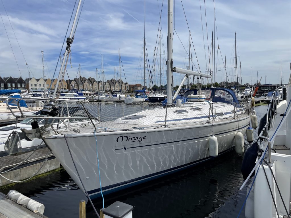
The weather had betrayed us. Our much anticipated one-week holiday to the Walton Backwaters had been turned into a one day trip by unseasonably high winds on the originally planned passage day, and now, as we finally enjoyed our first day on the beaches of Walton-on-the-Naze, the forecast once again showed high winds for the planned date for the return leg, and worst still, those high winds would be from the wrong direction. Mirage, our Bavaria 40, is a fine sea boat and would comfortably crash into a force 6 on the nose, however, I wanted to make sure for our four young crew (Thomas 10, Sophie 7, Matthew 4, and Isabelle 1) it would be a positive return journey. We had made the mistake of ignoring weather windows before to make the most of our holiday time, so we reluctantly planned to leave on the Thursday first thing, taking the first of the Ebb out of the Walton Backwaters to carry the flood up the Thames and back to our home port on the Medway.
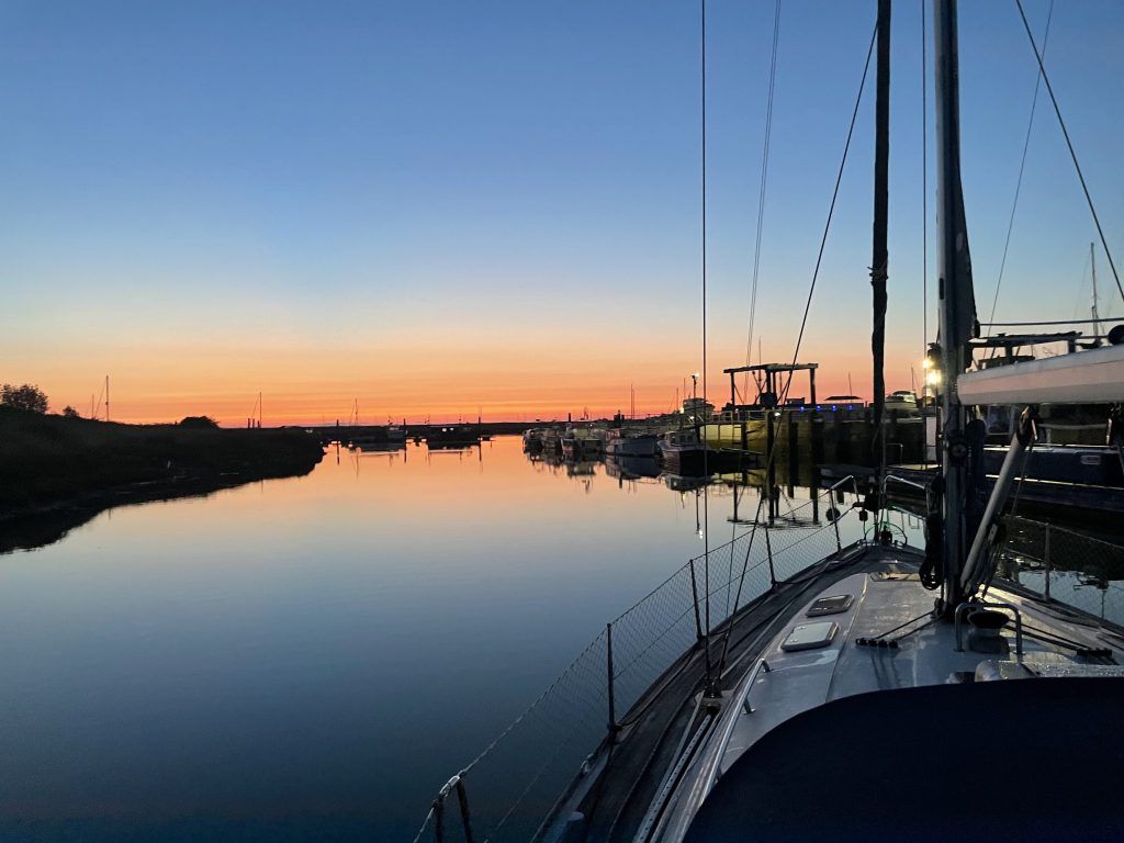


We departed as the false dawn crept up, with Liz, the first mate, helming the boat out of the marina and navigating the meandering channel over the bar of the Walton Backwaters. As we left, she complained the steering was exceedingly stiff. On the outward passage across the Thames we had noted the autopilot was squeaking and the steering was already feeling tight. We had problems with the autopilot drive unit clutch binding in the past, so I supposed it was this again, however the ever cheerful, helpful and expert Cliff of Whitlock Steering had rebuilt the unit for us the year before, so I was surprised.
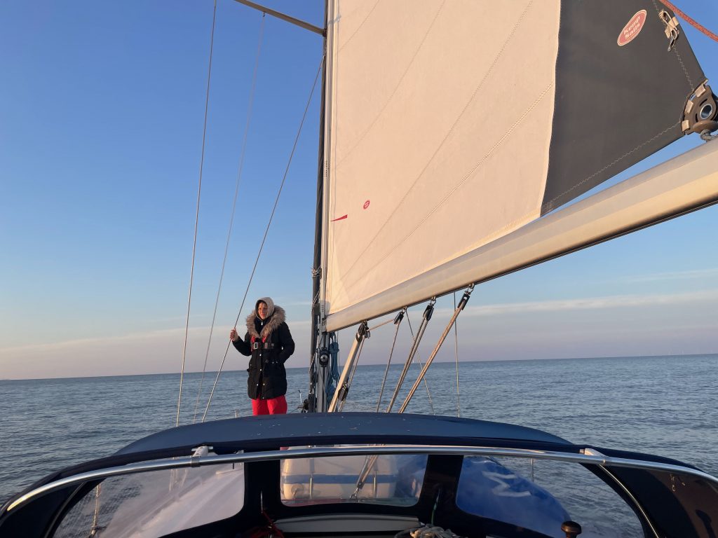
The conditions of the passage were ideal. A gentle breeze on the aft quarter over the fast-flowing tide that now flooded into the Thames made for flat seas and fast sailing, however, my anxiety grew as the autopilot groaned to port, and then groaned again to starboard. What would we do if the steering seized up before we got back to the marina?
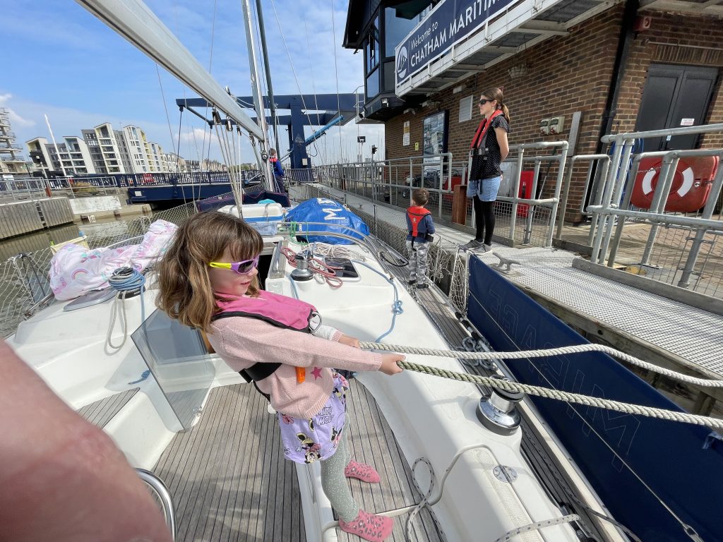
From the middle of the Thames I messaged Cliff, and (even though it was a bank holiday) he responded and politely dismissed my theory of the drive unit, and mused it was either cables or the rudder bearings. The steering stiffened up more as we approached the Medway, however, to my relief we glided safely into Chatham marina.
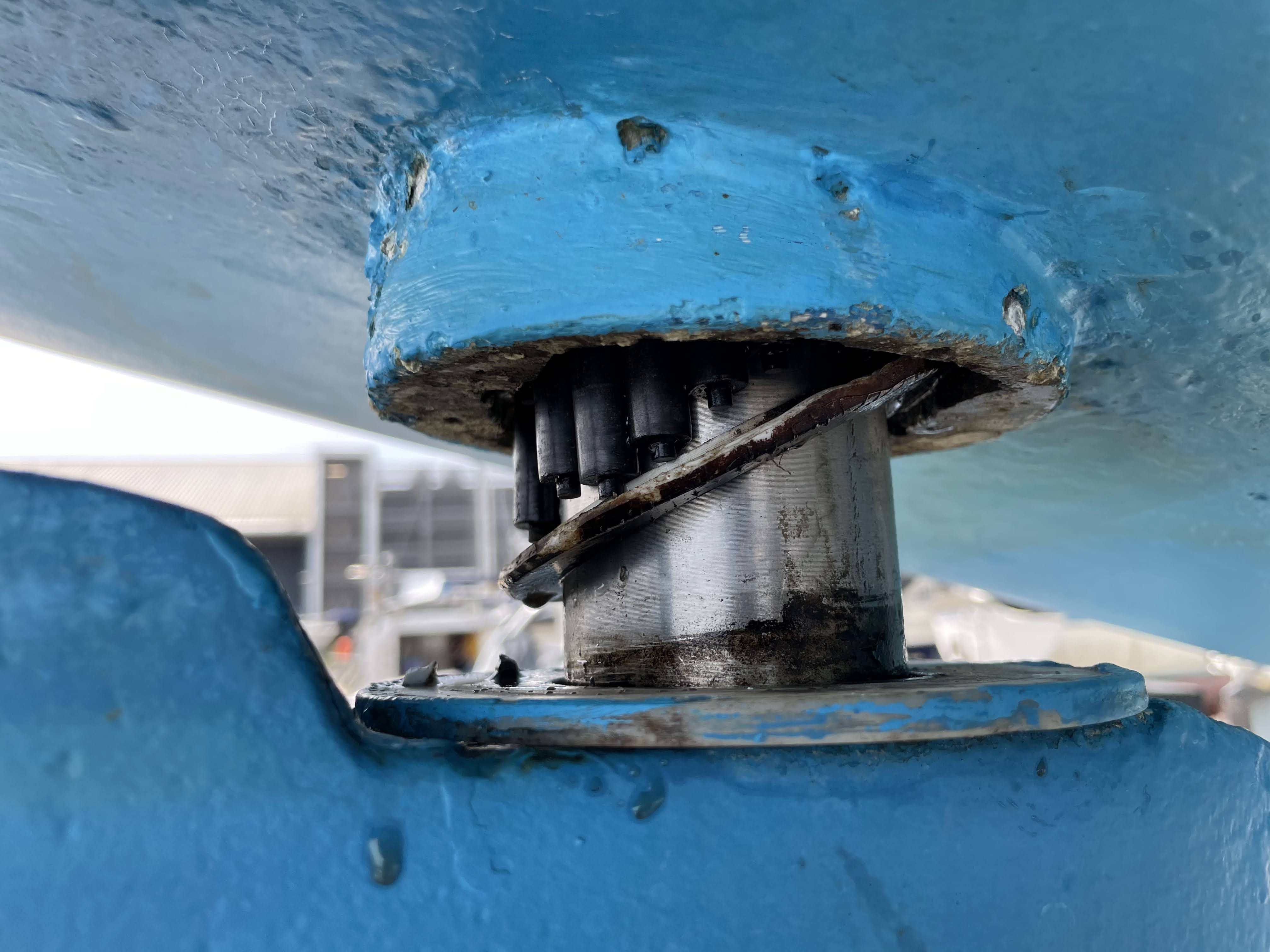
When we arrived, I disconnected the autopilot drive unit, and was dismayed that the groaning and stiffness remained. Finally, I disconnected the steering cables and man handled the quadrant to port and starboard and that proved it: It was still far too stiff, and still squeaking – the bearings were shot!
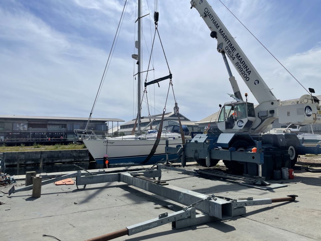
My first thought was that this was going to be a job that would be beyond me and too critical for me to cock up, so I started researching options for getting a yard to lift me out, drop the rudder and replace the bearings. There were a few challenges with this approach: The first was the price tag, as to get the job done by a yard was likely going to cost £2,000 plus, and secondly, I would need to deliver the boat to the yard to do the job, and at this point I was unsure how long my steering would last, so setting off on another passage did not feel seaman like, and thirdly, the wait these yards have at this time of the year; if I left someone else to do the job, I could write off the rest of my season. With this in mind, I set off on a fact-finding mission to understand what the job involved and what the risks associated were.
The anatomy of your spade steering system
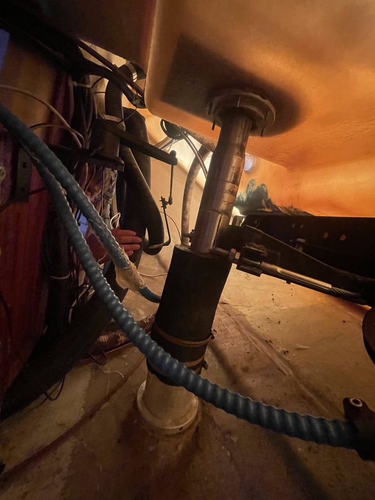
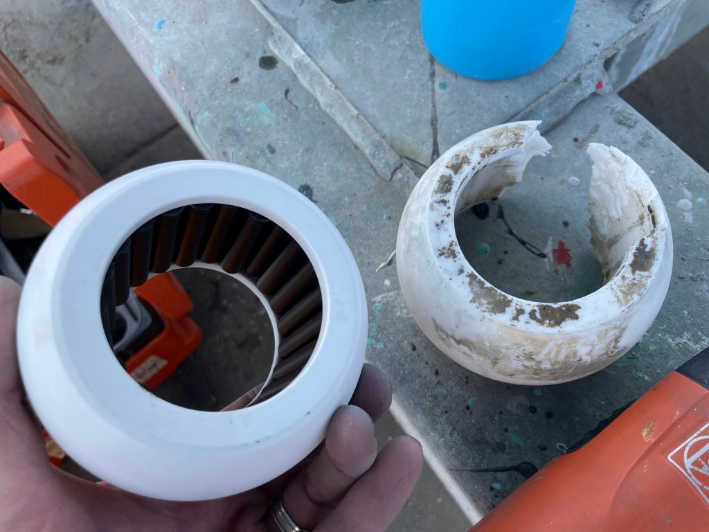
Since purchasing Mirage two years ago and moving from a thirty foot, tiller steered, Albin Ballad, the one system I had not had to rebuild and did not fully understand was the Whitlock (now Lewmar) Constellation wheel steering system. The system consists of a Jefa spade rudder hanging from the bottom of the boat, with an aluminium stock that passes through an aluminium bearing housing (in later models, they changed the material for composite, and you will see why they did that later on!), that contains an Acetal bearing, through an aluminium rudder tube, into the bottom of the boat.
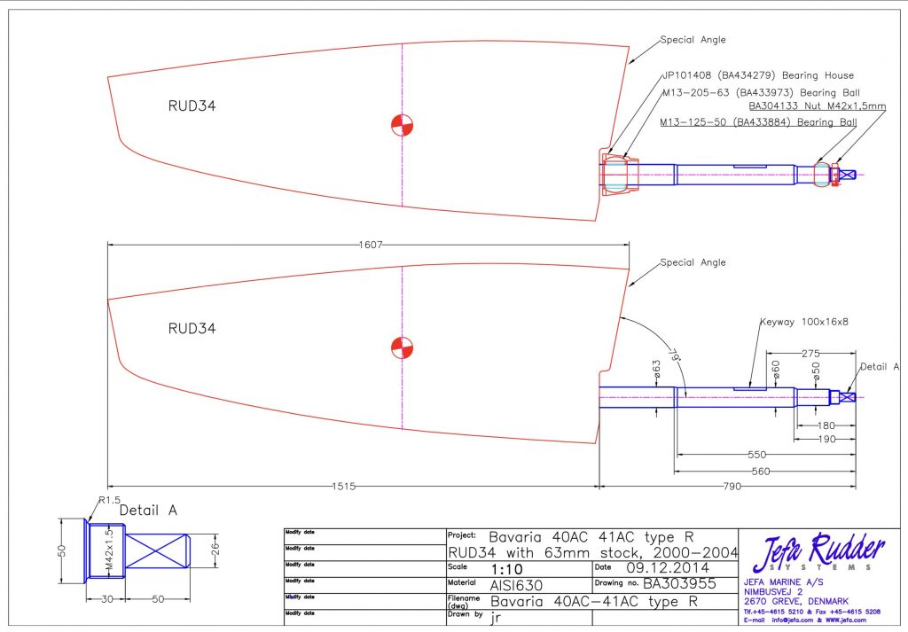
The stock then passes through a rubber tube, clamped on with two jubilee clips, with a lip seal (that Jefa refer to as a simmer-ring) on the top that is also clamped on with an additional jubilee clip.
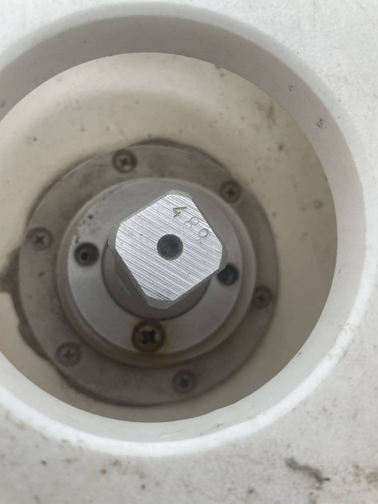
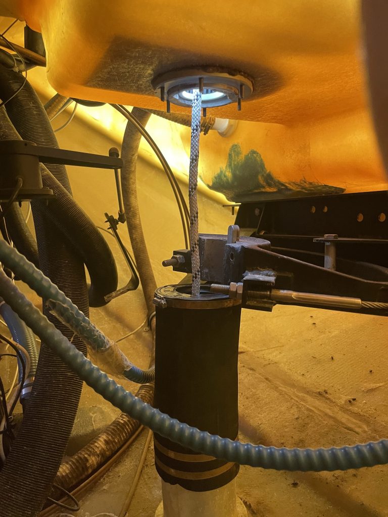
Above this sits a thing called a “quadrant” that is clamped around the rudder stock with four hefty machine screws and located with a key onto the aft end of the rudder stock to make sure it is perfectly aligned to the rudder below the boat. Onto that quadrant, cables are connected that run forwards to the binnacle (in Mirages case, through cable conduit), before being led up to a to a chain that is driven by a sprocket on the shaft of the wheel. Above the quadrant on the rudder stock, sits the autopilots rudder position sensor, clamped on with two jubilee clips.
The top of the shaft of the rudder then pokes up through the smaller upper bearing (that gets a very easy life in comparison to the lower bearing) into the back of the cockpit. The rudder is then secured with a circular nut that stops the rudder from falling out of the bottom of the boat, with a machine screw that acts as a “locking” screw to prevent the big nut spinning itself off.
Step 1: Time to devise a plan and build a hoist!
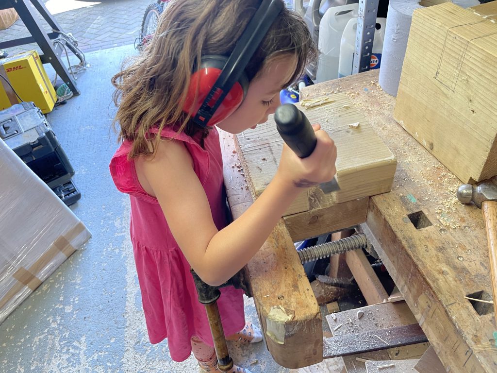
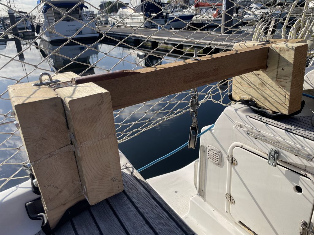
On the face of it, there were not that many moving parts. How hard could it be?! Doing it myself would not only save thousands of pounds, it would give me critical knowledge and expertise in an area of my boat I currently didn’t know well enough and by doing it myself, it would save the rest of my sailing season. The one element that worried me most was the fact it was a “heavy” job. Whilst the rudder stock was aluminium, it must still weigh 60 kilograms, with most of that weight being at the top. I needed to a method to lower and hoist the rudder in a controlled and safe way. Taking inspiration from another member of the Bavaria sailing community, I designed a hoist system that would span the transom from scraps in the “bat cave” and be secured to the push pit using a ratchet strap. One of the crew helped me manufacture the rough but effective hoist.
The finished article was then offered up to the boat, where I added a couple of “feet” to the forward part of the hoist to stabilise it, before adding some cut up wet suit to the bottom of the feet to protect the cockpit as much as possible during the lifting operations.
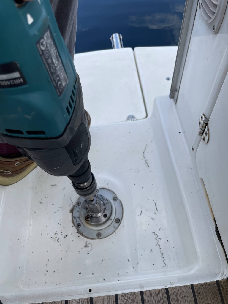
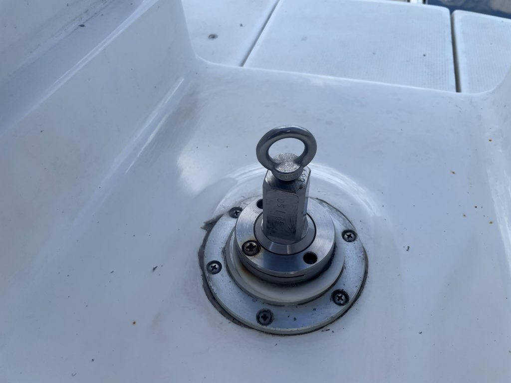
The next thing I needed was a method to attach a lifting eye to the top of the rudder stock to allow the hoist to bear the weight of the rudder. All there was in the top of the rudder stock was a small 6mm hole, a few millimetres deep that had no thread. To allow me to attach a stainless lifting eye, I drilled it carefully out to M8, using plenty of cutting fluid and a slow speed with heavy downward pressure, before cutting an M8 thread into the top of the stock.
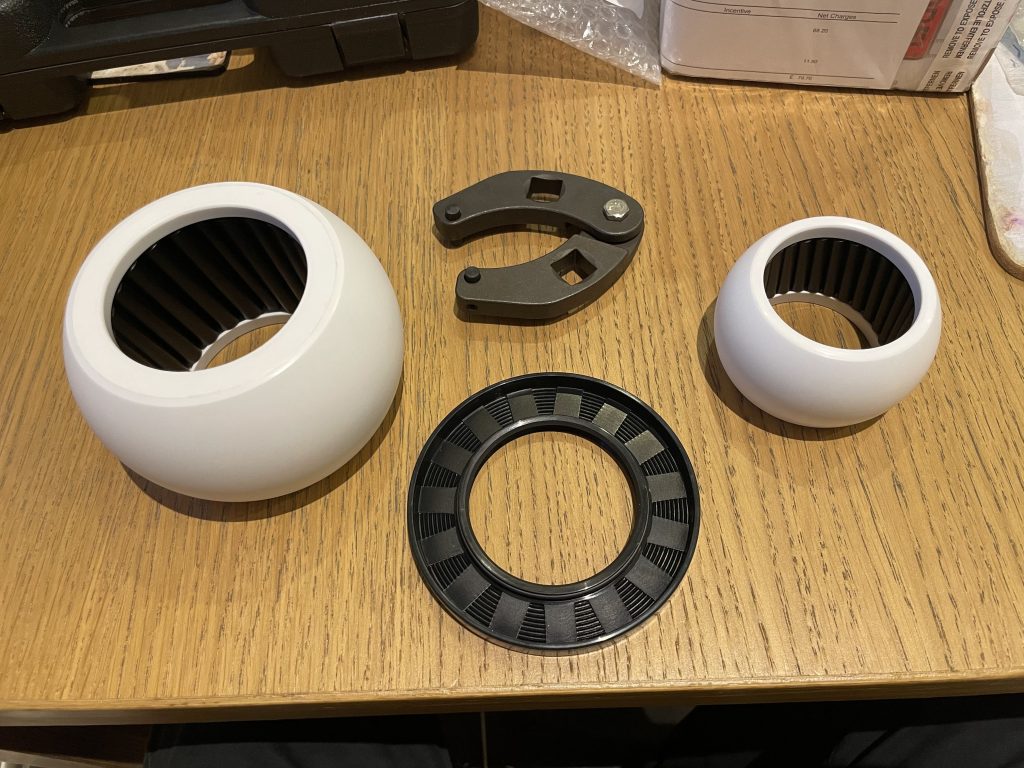
Finally, I contacted Jefa in Denmark to order the new bearings and a new lip seal for the top of the rudder tube. Whilst I knew the bottom bearing was the “trouble” bearing, I concluded I might as well replace the top bearing whilst I was at it. The cost of both bearings came to around £330, however, when they landed, a further £80 of duty was applied and had to be paid before the bearings would be released. I also ordered a tool specifically for taking off the top nut of the rudder stock, as there had been reports of owners needing to cut these nuts off as they had become stuck on the stock.
Fully armed with my plan and the new parts, and with a sense of impending doom, I marched off to the boat.
Step 2: Make sure all fastenings are free
Before getting anywhere near the lifting hoist, be sure that everything “moves” and cracks a little. There are many horror stories of machine screws being stuck in place and needing to be drilled out, or nuts needing to be surgically cut off from the rudder stock. The thought of drilling anything out in the cramped aft locker filled me with horror. The fastening that worried me most was the locking machine screw on the top nut as it looked rusty and was the delightful combination of steel into aluminium that will often cause fastenings to bind, so I had my doubts that would move.
I started by soaking all fastenings in PlusGas and leaving them for 24 hours in the hot summer sun to work its magic. I then headed back to the boat armed with an impact driver and a blow torch. Much to my amazement, the locking screw that had caused me so much dread began to move after only a few blows with my trusty Teng Tools impact driver.
Next, I cracked each of the machine screws holding on the quadrant on and finally all the jubilee clips, and everything moved! With that done, there was no more preparation I could do. I had my plan, I had all the parts and tools I needed, and I was as sure as I could be that all of the moving parts were not seized. I booked the lift out for the following Thursday and the lift back in for the Friday with the optimistic view that that was be more than enough time.
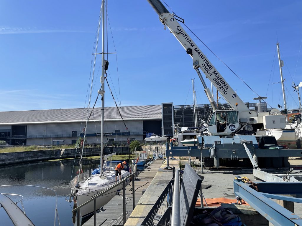
Step 3: Lift out and drop the rudder
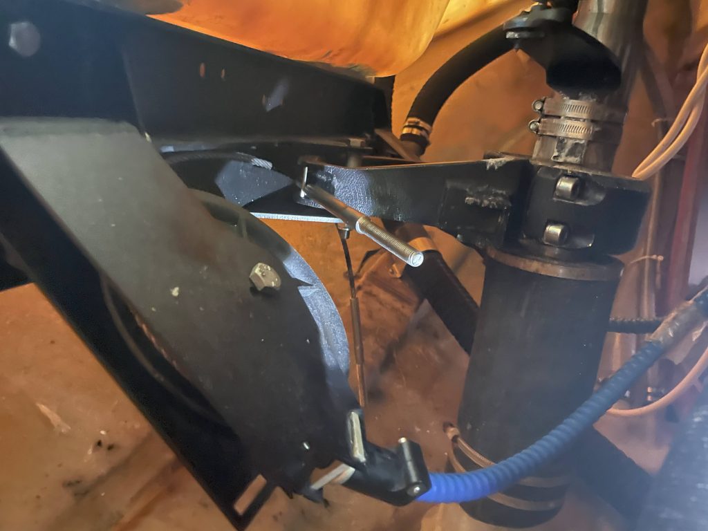
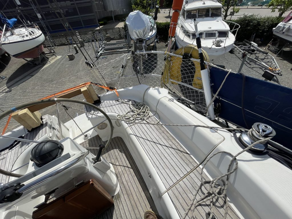
It was all going so well. I chugged her over to the crane, where Wayne, the yard manager, took my lines and we got the boat out of the water. After a quick wash off, we got some wooden blocks and supported the weight of the rudder. This part is essential, as if the whole weight of the rudder is resting on the top nut and with that weight putting pressure on the nut, there is very little chance it will come free. With the rudder chocked up, I hopped up the ladder and put my plan into action: I detached the jubilee clip holding the rudder tube onto the lip seal, I took off the two jubilee clips holding the rudder position sensor on, and then detached the four machine screws holding the quadrant on. This then required a gentle tap with a rubber mallet to separate it from the stock. With these all off, my work in the lazerette was complete.
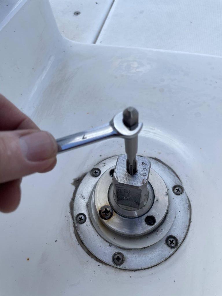
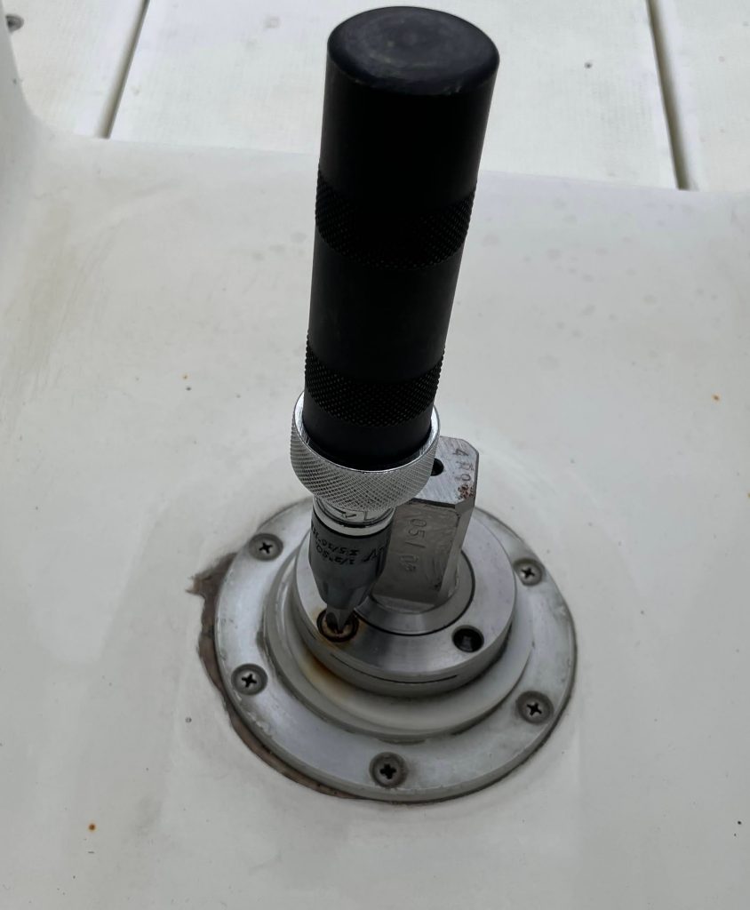
All that was holding the rudder on now was the top nut. Up I went into the cockpit armed with my new tool to release the nut, where to my surprise (and alarm) the nut was only finger tight as was easily spun off.
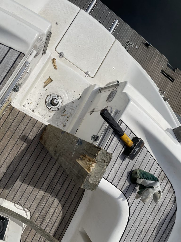
It was all going so well! I imagined I would be finished long before lunch and could spend the rest of my day celebrating my great victory. We carefully removed two of the wedges holding the rudder up and gently tapped the top of the rudder stock… nothing moved. Just for this occasion, I had bought along a lump of soft wood and a small club hammer, and thus the wailing with a hammer commenced. Whilst my sailing friend, Bob, waggled the rudder, I relentlessly hammered to top of the rudder. In fractions of millimetres it worked its way downwards.
After 45 minutes of smashing it had moved only a few millimetres. To try and lubricate the lower bearing, I prised the lip seal out of the top of the rubber tube and sprayed a hefty amount of silicone lube down the rudder tube. It is important that you use something that is not oil based, such as WD40, as that could be absorbed by the bearing and cause it to swell, and also it is not safe to use on rubber, such as the rubber tube on top of the aluminium rudder tube.
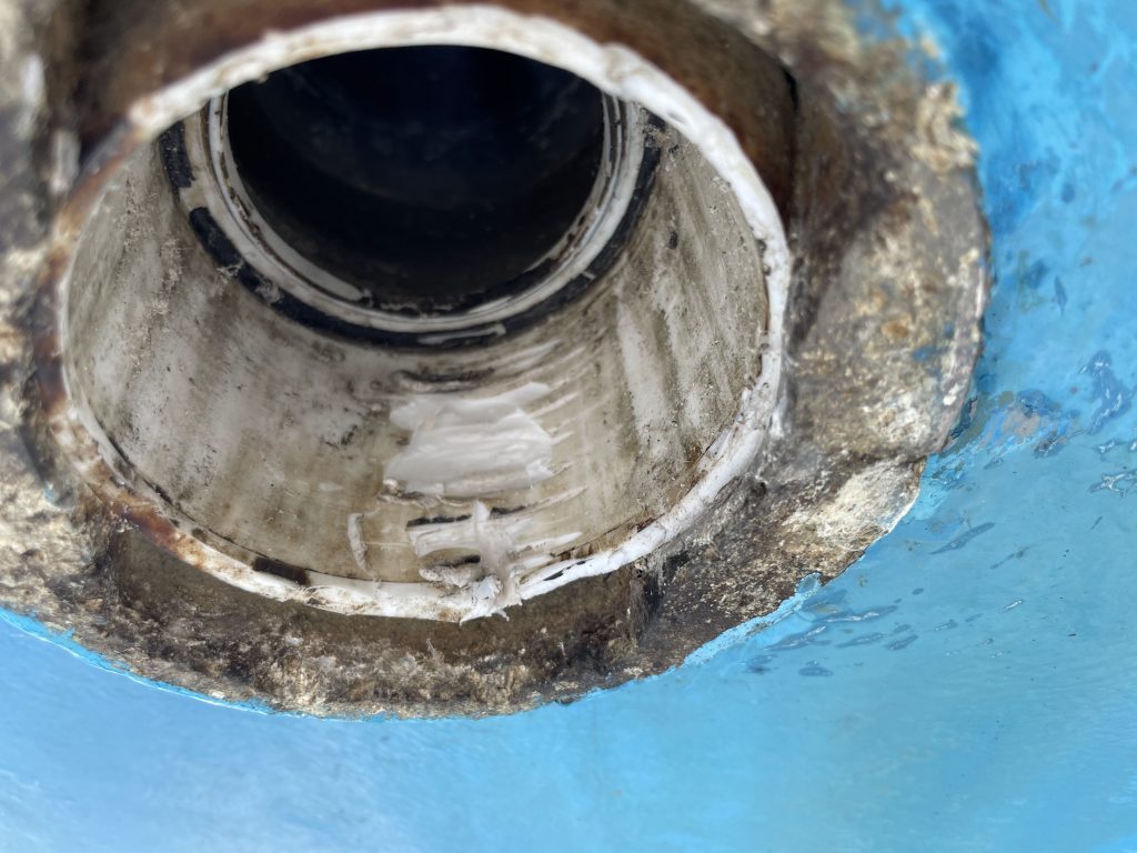
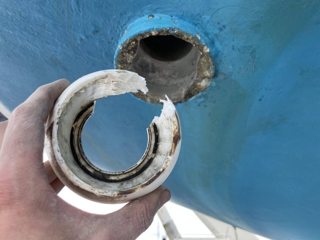
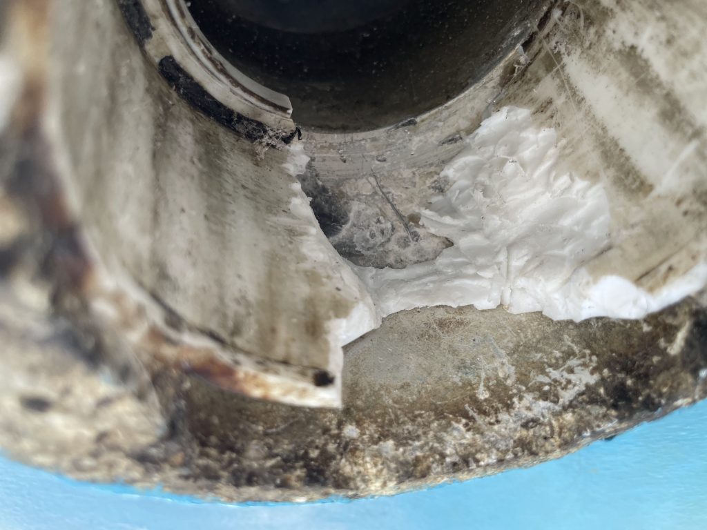
With a few more determined blows of the hammer, something suddenly gave and Bob called me down to take a look. It was clear now the bearing was not going to come out in a single part, but in many parts, as the bottom of the bearing cage had sheered off! Looking along the break line, it was apparent that the cage had partially broken some time ago.
I chose at this time to not put the hoist up and we called Wayne from the yard back to help us with the lowering of the rudder. In retrospect, the hoist would have allowed a more controlled and safe lowering of the rudder. As we waited for the extra muscle to help extract the rudder, we waggled the rudder a bit more to see how free it really was, when suddenly the rudder gave way and the platform of blocks under the rudder began to give way too! I was halfway up the step ladder and grabbed the rudder to try to take the weight (from the step ladder, not a good plan!), and as the step ladder teetered precariously to the side, Bob stabilised the rudder just in time. With the addition of a few extra wedges we secured the platform and agreed we would not fiddle anymore with the rudder until assistance arrived.
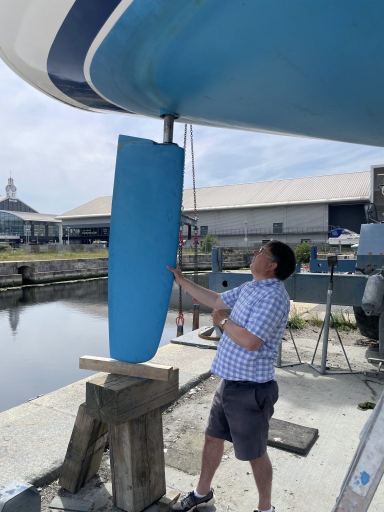
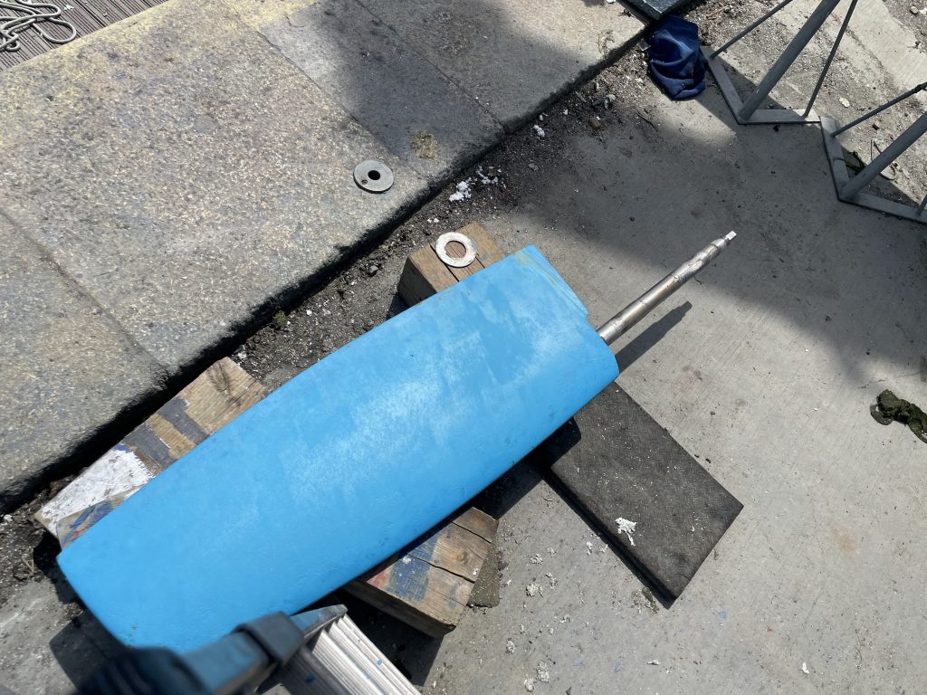
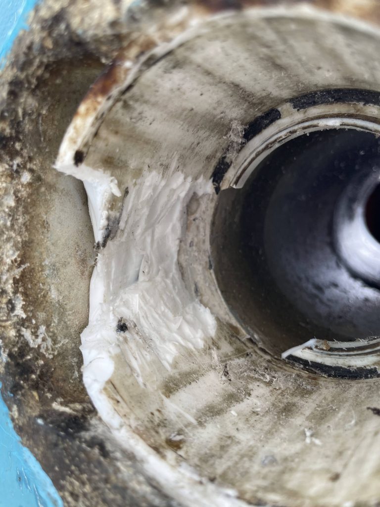
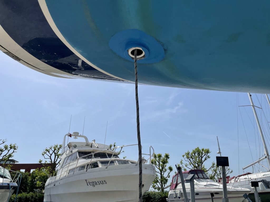
With Waynes help we lowered the rudder and set it down gently on some blocks of wood. Most rudders will be full of water, and sure enough, Mirages rudder sloshed around a bit as it came down. It’s important that you angle the rudder on the ground (or better still, stand it up), rather than leaving it horizontal on its side. If you leave it for any period of time on its side full of water, the water could cause osmosis as the water sits on one side of the blade. I was keen to use this opportunity to seal to top of the rudder stock onto the blade (to prevent this ingress of water), so I cleaned up the rudder and applied some Sikaflex around the join.
The rudder was off! It had taken about an hour of bashing, however, I still felt the job was going well and I expected to have the bearings changed in a jiffy and be putting the rudder back in the boat before the end of the day.
Step 4: Remove your bearing
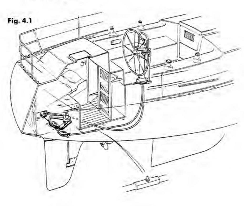
I had watched a video online published by Jefa, who manufacture rudders and bearings, that showed the method to extract the bearings for maintenance (a still from this video is below). All that was required was for the bearing to be turned through 90 degrees and the doughnut shaped bearing should just slide out of the aluminium bearing housing.
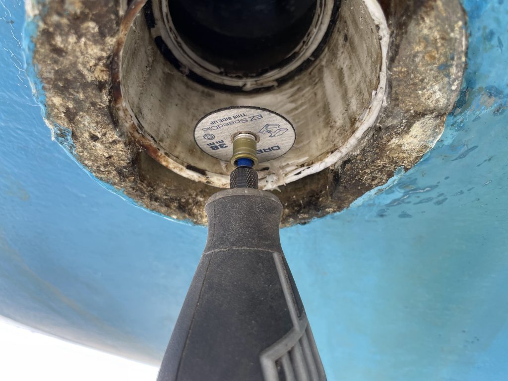
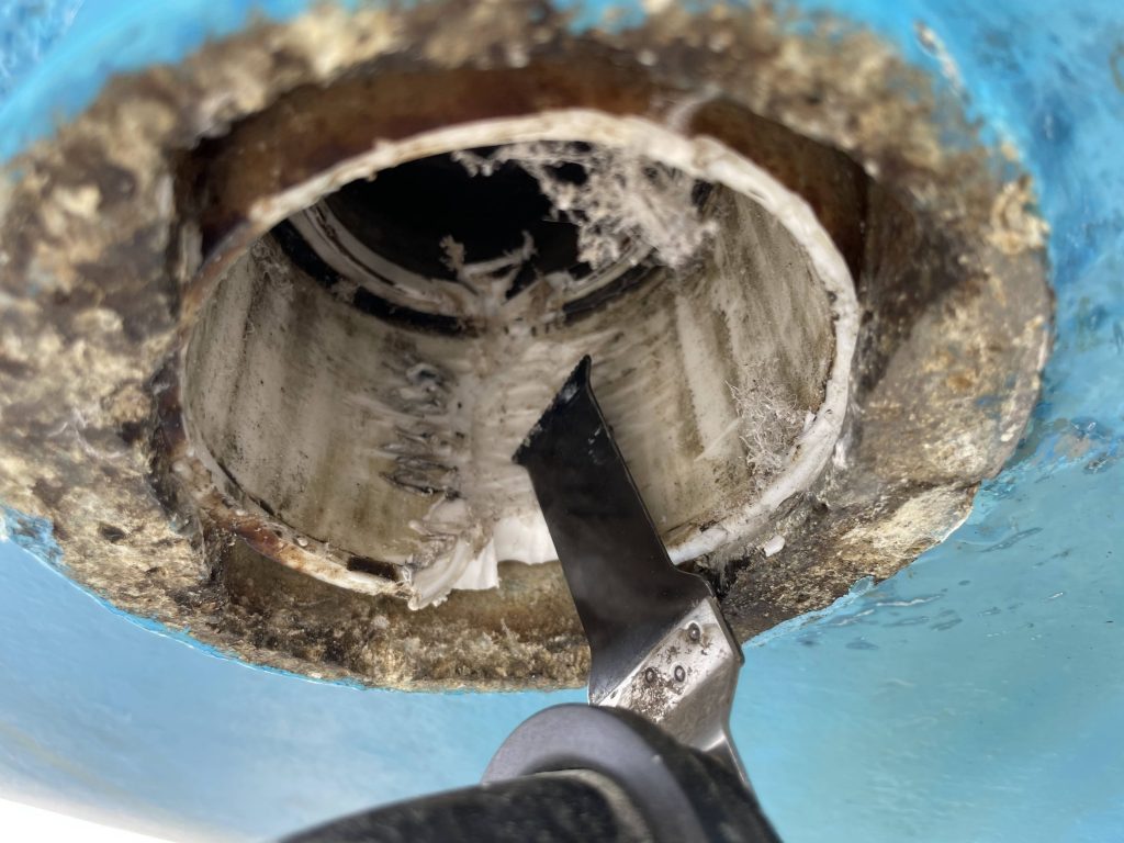
I approached my bearing and tried turning it. It was clear it was stuck and corrosion of the aluminium housing had welded the bearing in place, and so I heaved a sigh, picked up my favourite sharpened chisel, and set about very carefully chiselling a channel into the bearing. The aluminium housing is softer than the acetal bearing, so going carefully and slowly is very important. Destroying the housing would have turned this job from a challenge to a bit of a disaster.
I used a Dremel and a Fein multitool to cut relief cuts into the bearing, again, going very very carefully and slowly. Finally, as soon as the gully through the bearing was complete, with a few taps from a mallet the bearing began to turn and could be taken out.
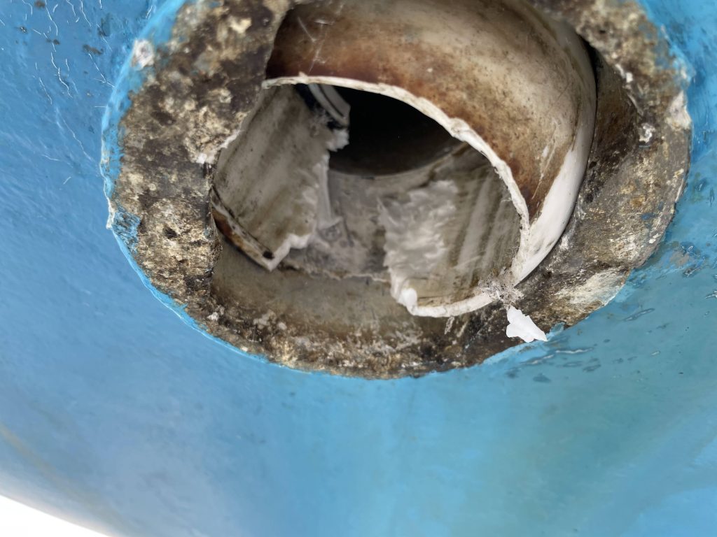
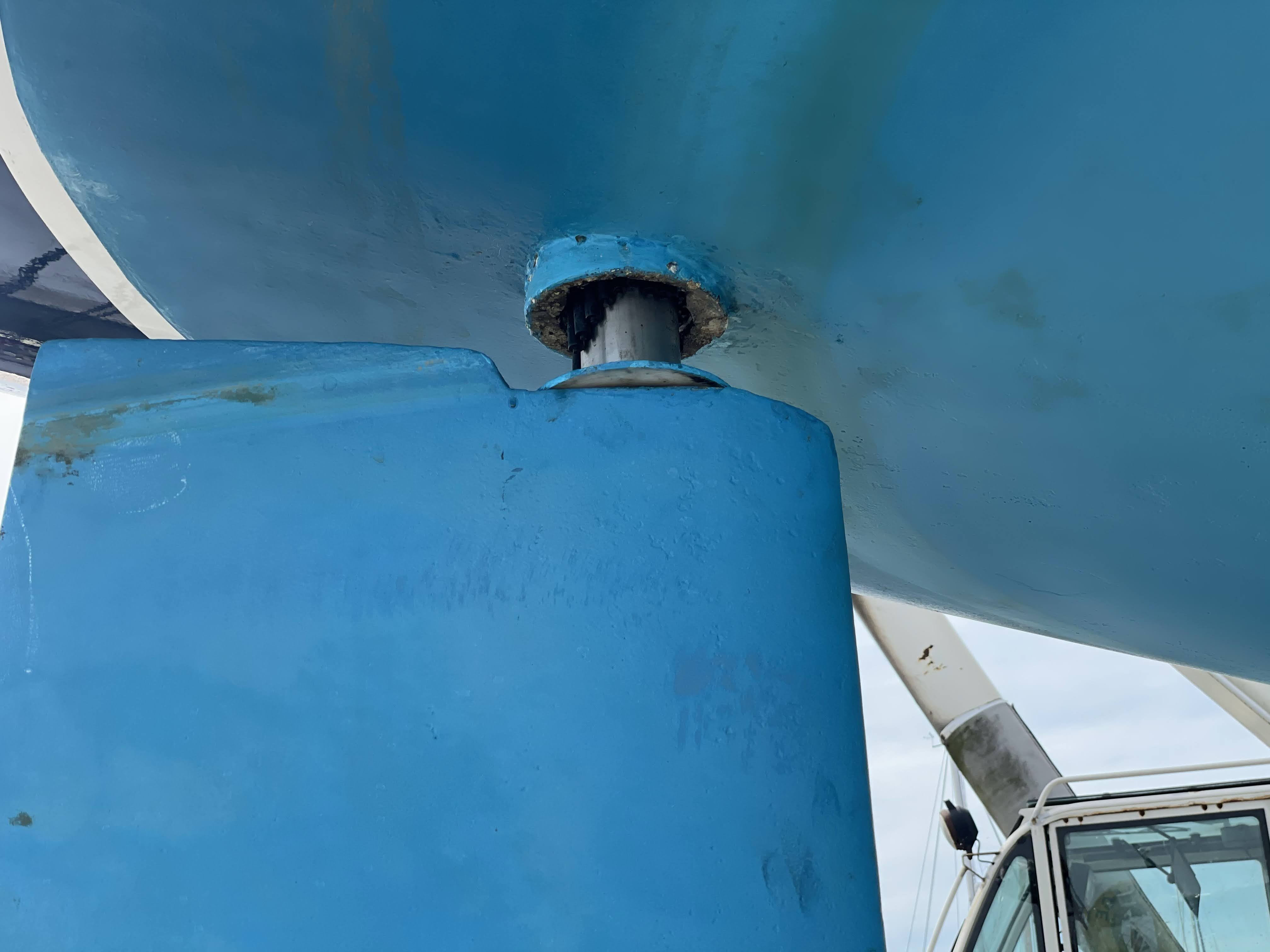
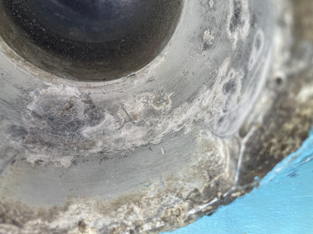
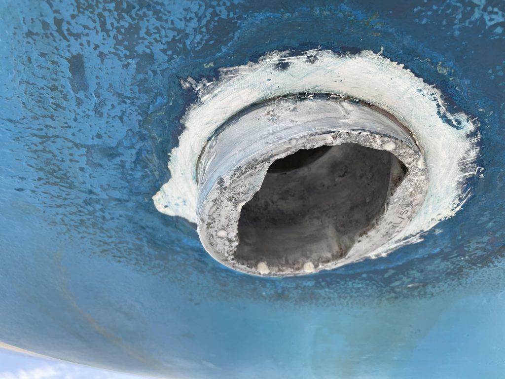
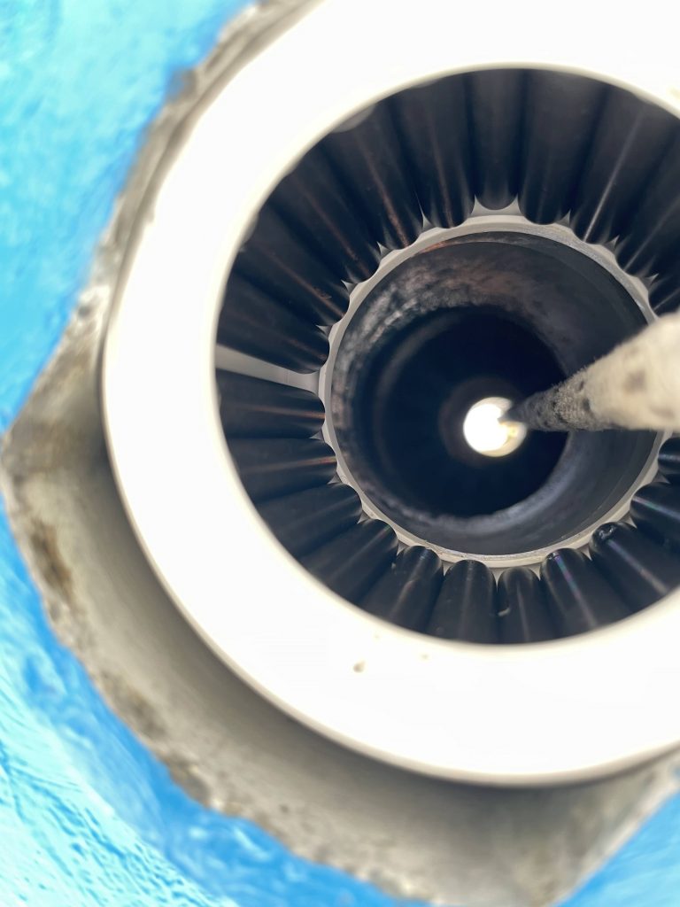
With the bearing out, the mode of failure could be very clearly seen. The normal antifouling (International Micro 350) had been painted right up to, and in some cases onto, the aluminium rudder tube. This contains copper as an active ingredient, and with that sitting directly beside the aluminium rudder tube, through a process of galvanic corrosion, where the more noble metal (in this case the copper) leaches from the less noble metal (our all important aluminium rudder tube) within an electrolyte (in this case, the sea!). This led to the aluminium rusting and the rust dust slowly crushing the bearing onto the rudder stock. Eventually the bottom of the bearing broke as it pressure built from the housing. By simply stripping all antifouling from the rudder tube a few years earlier when I purchased the boat I could have avoided this whole process.
Step 5 – Clean up the Bearing Housing
The bearing housing was in a sorry state. I had managed to avoid damaging it in the bearing extraction process, however it was apparent that the corrosion was quite extensive. After a brief sand down (that produced clouds of white dust) I inspected the housing. Thankfully the structural integrity of the bearing housing and the flanges that stopped the bearing dropping out appeared sound, so I set to work preparing the housing for the new bearing.
After 30 minutes of gentle sanding I judged the housing to be smooth enough and mostly back to bright aluminium. I offered back up the old bearing (that had the gully cut in it) and it went into the hole and turned neatly without binding, so I thought I had done enough and offered up my new bearing for a test fit.
This very nearly went disastrously wrong, as my new bearing nearly got wedged in the hole. Other owners have reported making the same gaff and having to destructively remove the new (very expensive) Jefa bearing. The relief cut in the old bearing allowed it to flex whereas the new bearing would, of course, have no flex in it at all. Using plastic tools and gentle persuasion, to my great relief, the bearing came free. I decided that discretion what the better part of valour and decided to not offer the bearing back to the housing until launch day, when I could return with some courser sandpaper.
Next, I had to make sure the process of galvanic corrosion that had murdered my original bearings did not reoccur, so I set about removing any and all antifouling from the aluminium and clearing an area at least 10mm around the housing. I filled any significant pits in the housing with epoxy and colloidal silica, leaving it for 24 hours before fairing it down and then painting on aluminium safe antifouling (in this case, International Trilux).
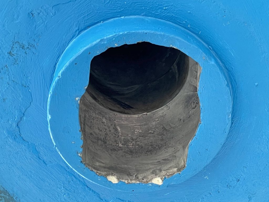
Content that every trace of copper based antifouling had been removed from the stern tube, I could now refit the new bearing… however I’d leave that to the next day when my courage would return.
Finally, I gently abraded the rudder stock itself where, it would contact the bearings, to make sure it was clear of any corrosion and contaminates and was nice and bright.
Step 6 – Fit your new bearing and refit the rudder
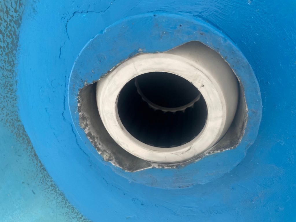
After having one more go at cleaning up the inside of the bearing housing and covering the bearing cages outer surface with the grease supplied by Jefa (making sure none of the grease got onto the bearing rollers themselves – these must only ever be lubricated by water), with my heart in my mouth I inserted the bearing and turned it. It turned smoothly into the housing without any play: Perfect!
With the everything in place, Wayne and Taylor of the yard helped me carry the rudder back over to the boat where I had set up the lifting hoist ready, with the eye secured into the thread at the top of the rudder stock.
I fed the rope from the winch through pulley on the hoist first, through the stop nut and acetal washer, that sits on the top of the stock that prevent the rudder from coming off (clearly you have to do this now, as you won’t be able to add the circular washer and nut after you have hoisted the rudder, as you can’t put it through the rope!) then down through the lazerette, though the new lip seal and out through the bottom of the rudder tube.
From there, it was secured to the lifting eye on the top of the rudder stock. It was the moment of truth. Would my lifting mechanism be up to the job of carrying the weight of the rudder? As it took the strain, I was glad I had the ratchet straps holding the mechanism down and back as the frame tried to come forward. It took the load and whilst the muscle of the yard was helpful getting the rudder into position, locating the stock into the top bearing and then keeping it in place and supporting the weight whilst the hoist was very useful for.
I tightened up the top nut and then applied a tiny amount of medium thread lock to the locking machine screw that squeeze the threads of the top nut together to lock it (after my experience with it being loose on extract it) and Mirage was all together with her rudder once again. As soon as it was in, the wind caught the rudder and it swung lazily around. That was much better – all was free once again. I used the emergency tiller to recentralise the steering and attach the quadrant, tightened up the jubilee clip holding the new lip seal on reattached the auto pilots rudder position sensor (you will need to recalibrate this, which is very straight forwards, however it will require referring to the manual) and she was ready to go.
What could have cost many thousands and robbed me of my season, or worse, if I had ignored until it completely seized at sea, had been completed in a couple of days of effort and at the cost of parts and a lift and relaunch.